
Makeup
Everything You Ever Wanted To Know About The ULN2003
Jun
The ULN2003 is one of those humble little integrated circuits that quietly makes electronics projects behave like adults. It does not brag. It does not wear a shiny heat sink hat. It does not ask to be called “smart.” Yet this 16-pin chip has rescued countless microcontrollers from the terrifying job of driving relays, lamps, solenoids, buzzers, LED segments, and small unipolar stepper motors directly from their delicate GPIO pins. In other words, the ULN2003 is the responsible friend who says, “No, Arduino, you should not lift that by yourself.”
At its heart, the ULN2003 is a seven-channel Darlington transistor array. That phrase sounds like something from a space opera, but the concept is practical: it lets low-power logic signals switch higher-current loads. A microcontroller pin may be fine for blinking a small LED, but a relay coil or motor winding can demand far more current than a GPIO pin should ever provide. The ULN2003 sits in between, taking tiny input signals and using them to sink current through external loads.
This guide explains what the ULN2003 is, how it works, why the ULN2003A is so popular, where it shines, where it struggles, and how to use it without creating smoke, sadness, or a breadboard that smells like toasted regret.
What Is the ULN2003?
The ULN2003 is a high-voltage, high-current Darlington transistor array. Most commonly, makers and engineers refer to the ULN2003A variant, which contains seven NPN Darlington pairs in a single package. Each channel works as a low-side switch: the load connects to the positive supply, and the ULN2003 output pulls the other side of the load down toward ground when activated.
That low-side switching behavior is the first big idea to understand. The ULN2003 does not source current to a load. It sinks current from the load to ground. When an input pin goes high, the corresponding output transistor turns on and completes the path to ground. When the input goes low, the output turns off and the load stops conducting.
Think of it like a drain in a bathtub. The water supply is your positive voltage, the load is the tub, and the ULN2003 is the drain plug. It does not pour water in; it lets current flow out. Weird analogy? Yes. Useful? Also yes.
Why Darlington Transistors Matter
A Darlington pair combines two bipolar transistors so the current gain of the first transistor feeds the second. The result is a very sensitive switching stage that can be controlled with a small input current while handling a larger output current. The ULN2003 repeats this arrangement seven times, giving you seven independent switching channels in one chip.
This is why the ULN2003 became a classic part for microcontroller projects. It saves board space, reduces part count, includes input resistors, and provides built-in clamp diodes for inductive loads. Instead of wiring seven separate transistor driver circuits, you can use one compact IC and get cleaner routing, fewer mistakes, and fewer tiny components trying to escape into the carpet.
Key ULN2003A Specifications
Seven Channels in One Package
The ULN2003A includes seven Darlington transistor channels. That is convenient for driving multiple relays, segments of a display, small lamps, or four coils of a unipolar stepper motor while still leaving extra channels for other loads.
500 mA Single-Channel Rating
A single output channel is commonly rated for up to 500 mA. That number is useful, but it should not be treated like a magic permission slip to run all seven outputs at 500 mA forever. Heat is still real. Package power dissipation, duty cycle, ambient temperature, and PCB layout all matter. The data sheet is your friend here, even if it looks like it was formatted by a committee of very serious ants.
50 V Output Capability
The ULN2003A is generally associated with high-voltage outputs up to 50 V, making it suitable for many relay coils, lamps, and industrial control loads that operate above logic voltage. This does not mean the chip creates 50 V. It means the output transistor can tolerate that voltage when used correctly.
Built-In Clamp Diodes
Inductive loads such as relays, solenoids, and motor coils fight back when switched off. Their collapsing magnetic fields can generate voltage spikes that may damage electronics. The ULN2003A includes clamp diodes connected to a common COM pin, helping route those spikes safely back to the load supply. It is the chip’s built-in “please do not zap my silicon” feature.
2.7 kΩ Input Resistors
The ULN2003A includes series input resistors designed for direct use with TTL and 5 V CMOS logic. This is one reason it pairs so easily with classic 5 V microcontroller boards. In many hobby circuits, you can connect a microcontroller output directly to a ULN2003 input without adding a separate base resistor.
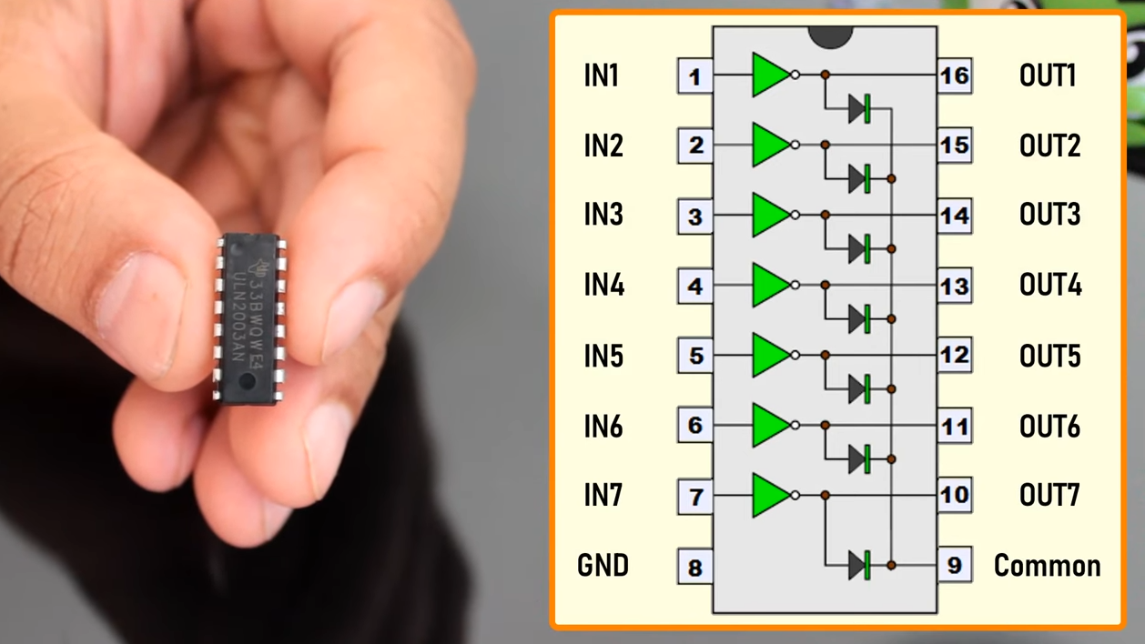
ULN2003 Pinout Explained
In the common 16-pin package, pins 1 through 7 are inputs. Pins 10 through 16 are outputs, arranged opposite the inputs to simplify PCB layout. Pin 8 is the common emitter connection, usually tied to ground. Pin 9 is COM, connected to the common cathodes of the internal clamp diodes.
The “opposite pin” layout is more helpful than it first appears. Input 1 corresponds to output 1 on the other side of the package, input 2 corresponds to output 2, and so on. This makes routing from a microcontroller on one side and loads on the other side much tidier.
For resistive loads like simple LEDs or lamps, the COM pin may not be needed. For inductive loads, connect COM to the positive supply used by the load. If you are driving a 12 V relay, COM typically goes to +12 V. If you are driving a 5 V stepper motor, COM goes to +5 V. Leaving COM floating with inductive loads defeats one of the chip’s best safety features, which is like buying an umbrella and refusing to open it in a thunderstorm.
How the ULN2003 Works in a Circuit
A typical ULN2003 circuit is simple. Connect the microcontroller ground to ULN2003 pin 8. Connect a digital output pin from the microcontroller to one ULN2003 input. Connect the load between the positive supply and the matching ULN2003 output. When the microcontroller output goes high, the ULN2003 sinks current and the load turns on.
Because the outputs are open collector, the chip does not drive a high level by itself. The load and supply provide the high side. The ULN2003 only pulls down. This is perfect for many relays, lamps, and motor coils, but it is the wrong choice when you need a push-pull output, bidirectional motor control, or precise current regulation.
Common ULN2003 Applications
Relay Drivers
Relays are one of the ULN2003’s classic jobs. A microcontroller output cannot safely energize most relay coils directly, but it can trigger a ULN2003 input. The relay coil connects between the relay supply and a ULN2003 output. COM connects to the relay supply voltage so the internal clamp diode can tame the coil’s flyback spike.
Solenoids and Small Actuators
Solenoids are electrically noisy little devices that move things with magnetic force. Door locks, valves, and small mechanisms often use them. The ULN2003 can switch modest solenoids as long as current and thermal limits are respected. For larger solenoids, use a MOSFET driver or dedicated power stage.
LED Displays and Indicator Banks
The ULN2003 can sink current for LED segments or indicator arrays. However, it is not a constant-current LED driver. Each LED or LED string still needs proper current limiting. Forgetting the resistor is how LEDs become one-time-use flashbulbs.
Small Lamps and Buzzers
Filament lamps and buzzers are also common loads. Lamps can have high inrush current when cold, so check the load behavior, not just the steady-state rating. The ULN2003 is rugged for its size, but it is not a superhero cape for bad power design.
Unipolar Stepper Motors
The famous 28BYJ-48 stepper motor and ULN2003 driver board are practically a rite of passage in Arduino projects. The motor’s common wire connects to the positive supply, while four coil wires connect to ULN2003 outputs. The microcontroller energizes the coils in sequence through ULN2003 inputs, making the motor step.
This setup is cheap, accessible, and excellent for learning. It is not a high-performance stepper driver. The ULN2003 does not perform microstepping, current chopping, or advanced torque control. For precision CNC, robotics, or fast motion, use a real stepper driver. For moving a small pointer, rotating a light-duty dial, or building a beginner project, the ULN2003 and 28BYJ-48 are a delightful little duo.
ULN2003 vs ULN2803
The ULN2803 is closely related to the ULN2003. The easiest difference to remember is channel count: ULN2003 has seven channels, while ULN2803 has eight. The ULN2803 usually comes in an 18-pin package and is popular when driving eight lines from a shift register, microcontroller port, or LED/display arrangement.
Choose the ULN2003 when seven channels are enough or when you are using common ULN2003 stepper driver boards. Choose the ULN2803 when eight channels make routing or software cleaner. In many designs, the decision is less dramatic than people expect. It is not Batman versus Superman; it is more like choosing between a seven-slot toolbox and an eight-slot toolbox.
ULN2003 vs MOSFET Drivers
The ULN2003 is convenient, but modern MOSFET driver arrays can be more efficient. Darlington transistors have a noticeable saturation voltage when on. That voltage drop wastes power and reduces the voltage available to the load. In a 5 V motor circuit, losing around a volt across the driver can matter. In a relay circuit, it may not matter much at all.
A logic-level MOSFET can offer lower on-resistance, less heat, and better performance for higher-current loads. If you need efficiency, low voltage drop, PWM motor control, or heavier current, a MOSFET solution may be the smarter choice. If you need simple, cheap, rugged low-side switching for several modest loads, the ULN2003 remains wonderfully useful.
Design Tips for Reliable ULN2003 Circuits
Share Grounds Correctly
If your microcontroller and load supply are separate, their grounds must usually be connected together so the ULN2003 input signals have a common reference. Without a shared ground, the chip may behave unpredictably, which is engineering-speak for “the ghost in the breadboard is back.”
Use External Power for Motors
Small stepper motors can pull more current than a development board’s regulator or USB port should provide. Use an external supply sized for the motor, and connect the supply ground to the controller ground. This keeps the microcontroller from browning out every time the motor gets ambitious.
Respect Heat Limits
Do not assume seven channels at maximum current is automatically safe. Check total package power, ambient temperature, duty cycle, and board layout. Heat builds quietly. By the time your fingertip discovers the problem, your design review has already become a cooking show.
Connect COM for Inductive Loads
For relays, solenoids, and motors, connect COM to the positive load supply. This lets the internal clamp diodes do their job. If you need faster relay release, you may use external clamp networks designed for that purpose, but beginners should first master the standard diode clamp approach.
Remember the Output Inverts Logic
Input high means the output transistor turns on and pulls the load side low. The load energizes. Input low means the transistor turns off. This inversion is simple, but it can confuse software debugging if you expect the output pin to “go high” at the load.
Common Mistakes to Avoid
The first mistake is treating the ULN2003 like a motor driver for every motor. It is a low-side switch array, not a full H-bridge. It cannot reverse a simple two-wire DC motor by itself. For bidirectional DC motor control, use an H-bridge or motor driver module.
The second mistake is forgetting current-limiting resistors for LEDs. The ULN2003 switches current; it does not regulate it. LEDs still need resistors or a proper current driver.
The third mistake is connecting loads to ground and expecting the ULN2003 to provide positive voltage. It will not. Loads go between positive supply and output. The ULN2003 pulls the output down.
The fourth mistake is ignoring voltage drop. A Darlington output does not behave like a perfect wire to ground. If your 5 V motor feels weaker than expected, the driver’s voltage drop may be part of the story.
The fifth mistake is powering motors from the microcontroller board. Sometimes it works on the desk and fails inside the final project, which is electronics’ favorite prank. Use a proper external supply when the load deserves one.
When the ULN2003 Is the Right Choice
The ULN2003 is a great choice when you need multiple low-side switches, modest current, simple control, and built-in inductive load protection. It is especially attractive for relay banks, small actuator projects, educational kits, simple LED display sinking, and 28BYJ-48 stepper motor boards.
It is also a fantastic teaching component. Students can learn about transistor switching, flyback protection, common ground, current sinking, and load isolation without building seven discrete transistor circuits. The chip turns several beginner pain points into one understandable package.
When You Should Choose Something Else
Choose a MOSFET when efficiency and low voltage drop are important. Choose an H-bridge for bidirectional DC motors. Choose a current-regulating stepper driver for bipolar steppers, microstepping, or high-performance motion. Choose an opto-isolated driver when electrical isolation is required. Choose a dedicated LED driver when brightness matching and current regulation matter.
The ULN2003 is versatile, not universal. A spoon is excellent for soup, but nobody should use one to cut plywood.
Field Notes: Real-World Experience With the ULN2003
In real projects, the ULN2003 often shows up in the exact moment when a design moves from “the microcontroller blinks an LED” to “the microcontroller must control something that clicks, spins, buzzes, pulls, or glows with authority.” That transition is where many beginners learn the difference between logic and power. Logic says, “I have a signal.” Power says, “Wonderful, but can you move this coil?” The ULN2003 answers, “Yes, within reason.”
One of the most common experiences is using the ULN2003 driver board with the 28BYJ-48 stepper motor. The wiring looks almost too easy: four input pins from the controller, a motor connector, power, and ground. The board’s indicator LEDs blink in sequence, the motor turns, and the project suddenly feels alive. Then the first lesson arrives: the motor may chatter, stall, or reset the controller if powered from a weak USB supply. The fix is not mysterious. Use an external 5 V supply with enough current and share the ground with the microcontroller. That one lesson alone is worth the price of the module.
Another practical lesson comes from relay boards and loose relay coils. When wired correctly, the ULN2003 makes relay control beautifully simple. But if the COM pin is not connected to the relay supply, switching may become noisy or unreliable. Sometimes the circuit appears to work for a while, which is the most annoying kind of wrong. Connecting COM properly gives the internal clamp diodes a return path and makes the circuit far more civilized.
Heat is the next teacher. A single modest relay coil is no big deal. Several channels running continuously can make the chip warm. Add a high ambient temperature, cramped enclosure, and optimistic current assumptions, and suddenly the little black IC becomes a tiny space heater. The best habit is to calculate total load current, think about duty cycle, and avoid pushing every channel to the limit. The ULN2003 is dependable when respected. It is less cheerful when treated like a seven-lane freeway with no speed limit.
The voltage drop across Darlington outputs also surprises people. In a 12 V relay circuit, the drop may barely matter. In a 5 V motor circuit, it can reduce torque noticeably. This is why a 28BYJ-48 on a ULN2003 board is great for light-duty movement but not ideal for demanding mechanical work. If the project needs more torque, better speed control, or battery efficiency, a MOSFET-based driver or a dedicated stepper driver is usually the upgrade path.
The best experience-based advice is simple: use the ULN2003 for what it is excellent at. It is a friendly, low-cost, multi-channel low-side switch for modest loads. Keep grounds common, wire inductive loads correctly, avoid fantasy current budgets, and remember that outputs sink rather than source. Do that, and the ULN2003 will quietly make your project work while receiving almost none of the applause. That is okay. Some of the best components are the ones that never become dramatic.
Conclusion
The ULN2003 has earned its long life in electronics because it solves a common problem cleanly: microcontrollers are good at decisions, but not at directly powering chunky real-world loads. With seven Darlington channels, built-in input resistors, open-collector outputs, and clamp diodes for inductive loads, the ULN2003A remains a practical bridge between logic signals and devices that need more current.
It is not the newest or most efficient driver option. MOSFET arrays and dedicated motor drivers can outperform it in many modern designs. Still, for relays, small solenoids, indicator banks, lamps, simple unipolar stepper motors, and educational circuits, the ULN2003 is still the friendly little workhorse that gets the job done. It is cheap, understandable, widely available, and forgiving enough for beginners while still useful enough for professionals.
Use it wisely, respect its limits, and connect that COM pin when switching coils. Your microcontroller will thank you, your relays will click politely, and your project will be less likely to release the sacred smoke.
